
When measuring a fibre optic link with an OTDR, you will connect a launch cable between the OTDR and the first connector in the link, usually this is at a patch panel.
The loss at the connector shown on the OTDR can seem high and this is because you are really measuring two things at once — the connector, and the splice hiding right behind it. Here’s how to tell them apart before you flag a good connector as faulty.
Why the OTDR reading includes the splice
Measuring a system connector with an OTDR can’t be done directly — the OTDR has to be connected to the connector under test through a launch cable. That launch cable’s far end is usually connected to a termination joint at an in-line adapter. At the back of the adapter is a pigtail which consists of a connector fitted to a short length of secondary coated 900 micron fibre, 1 metre or less, cut to suit the termination joint and fusion spliced onto the fibre from the main route cable. The OTDR trace runs straight through both:
So every connector-loss figure an OTDR reports is really a combined reading — the connector’s own insertion loss, plus whatever the splice immediately behind it is contributing. A connector that’s actually within spec can still produce a reading that looks too high, if the splice behind it is the real culprit.
Reference loss & reflectance figures
Use these as the baseline for what a connector on its own should contribute, before any splice loss is added in.
Singlemode
| Connector type | Insertion loss, typical (dB) | Insertion loss, max (dB) | Reflectance, typical (−dB) | Reflectance, max (−dB) |
|---|---|---|---|---|
| FC/PC | 0.35 | 0.55 | 40 | 35 |
| SC/PC | 0.35 | 0.55 | 40 | 35 |
| ST/PC | 0.35 | 0.55 | 40 | 35 |
| FC/SPC | 0.35 | 0.55 | 45 | 40 |
| ST/SPC | 0.35 | 0.55 | 45 | 40 |
| FC/UPC | 0.35 | 0.55 | 50 | 45 |
| ST/UPC | 0.35 | 0.55 | 50 | 45 |
| FC/APC | 0.35 | 0.55 | 60 | 50 |
| SC/APC | 0.35 | 0.55 | 60 | 50 |
Multimode
| Connector type | Insertion loss, typical (dB) | Insertion loss, max (dB) | Reflectance, typical (−dB) | Reflectance, max (−dB) |
|---|---|---|---|---|
| FC/PC | 0.6 | 1 | 30 | 20 |
| SC/PC | 0.6 | 1 | 30 | 20 |
| ST/PC | 0.6 | 1 | 30 | 25 |
| FC/SPC | 0.6 | 1 | 35 | 30 |
| ST/SPC | 0.6 | 1 | 35 | 30 |
Insertion loss is dB lost crossing the connector; reflectance (return loss) is how much light reflects straight back — the bigger the −dB figure, the less reflection, so APC connectors (60dB) reflect far less than PC connectors (35–40dB).
Worked example
Take a singlemode connector at its worst-case insertion loss, with a typical splice behind it:
If an OTDR reports 0.75dB at that joint, the connector itself could still be perfectly within spec — it’s the combined figure that matters when deciding whether to re-work anything.
Testing tip: dissimilar fibres
If the pigtail fibre and the route cable fibre come from different manufacturers, the splice can read higher than the typical figure above even when it’s a good splice — the mismatch between two slightly different fibre types shows up as extra apparent loss. When that’s a possibility, test the joint in both directions and average the two readings, rather than trusting a single-direction trace.
Opticus OTDR equipment
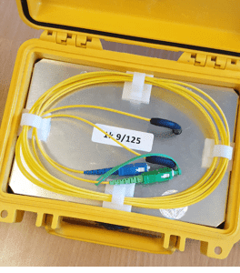
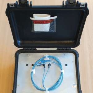
If you need a launch cable to make this measurement — ours are built specifically for connecting an OTDR to the cable under test:
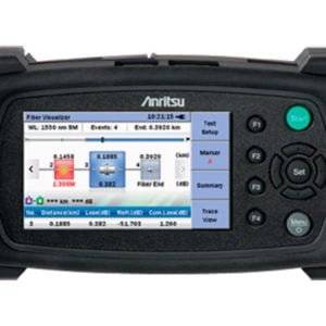
OTDRs for connector & splice testing
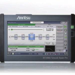
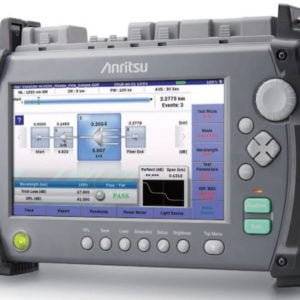
Our OTDR range, from a compact micro OTDR up to a high-resolution long-distance unit:



Fibre Masterclass Note 44 — for printing or offline reference
Not sure which OTDR or launch cable fits your test?
Tell us what you’re testing and we’ll recommend the right setup.